MartiLuxe
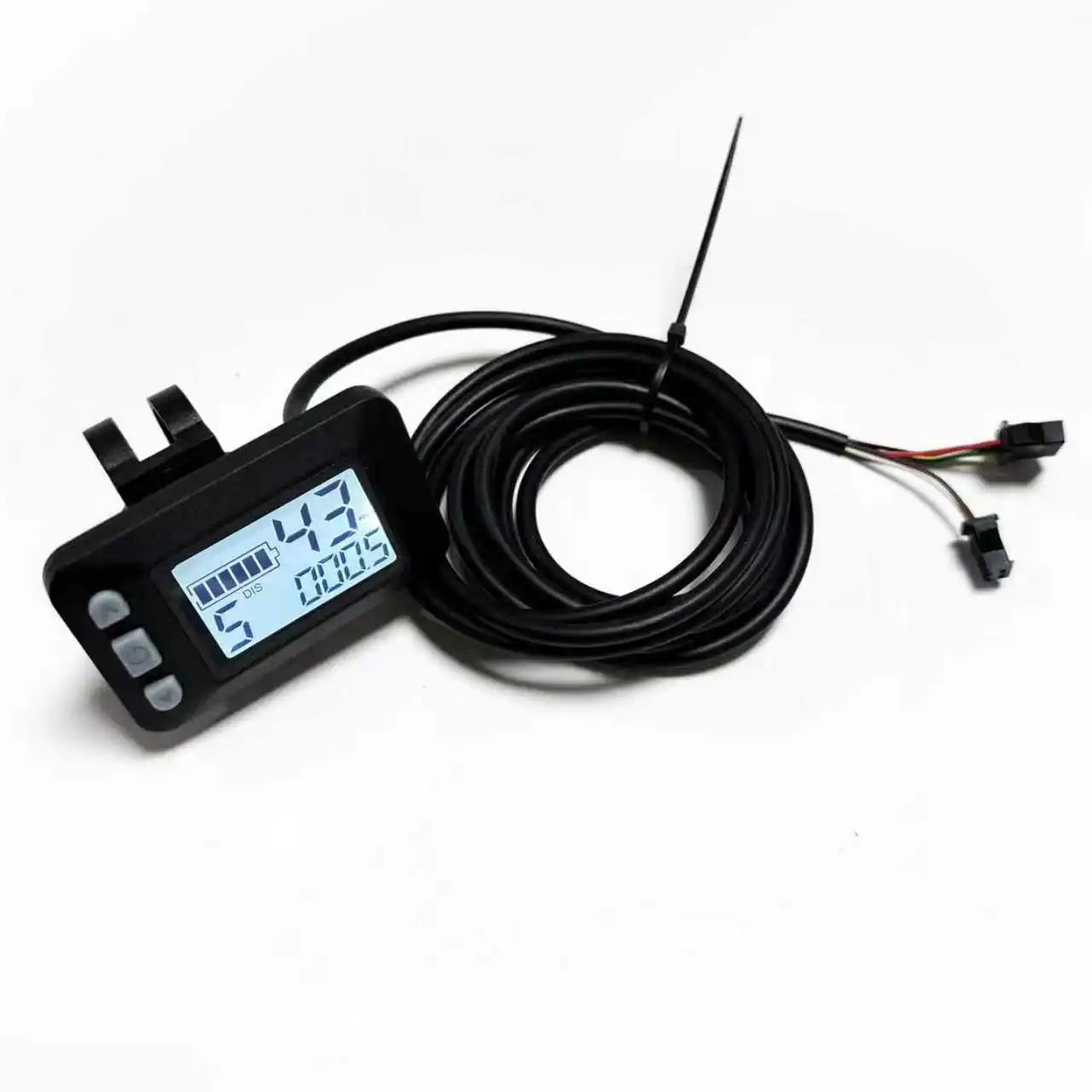
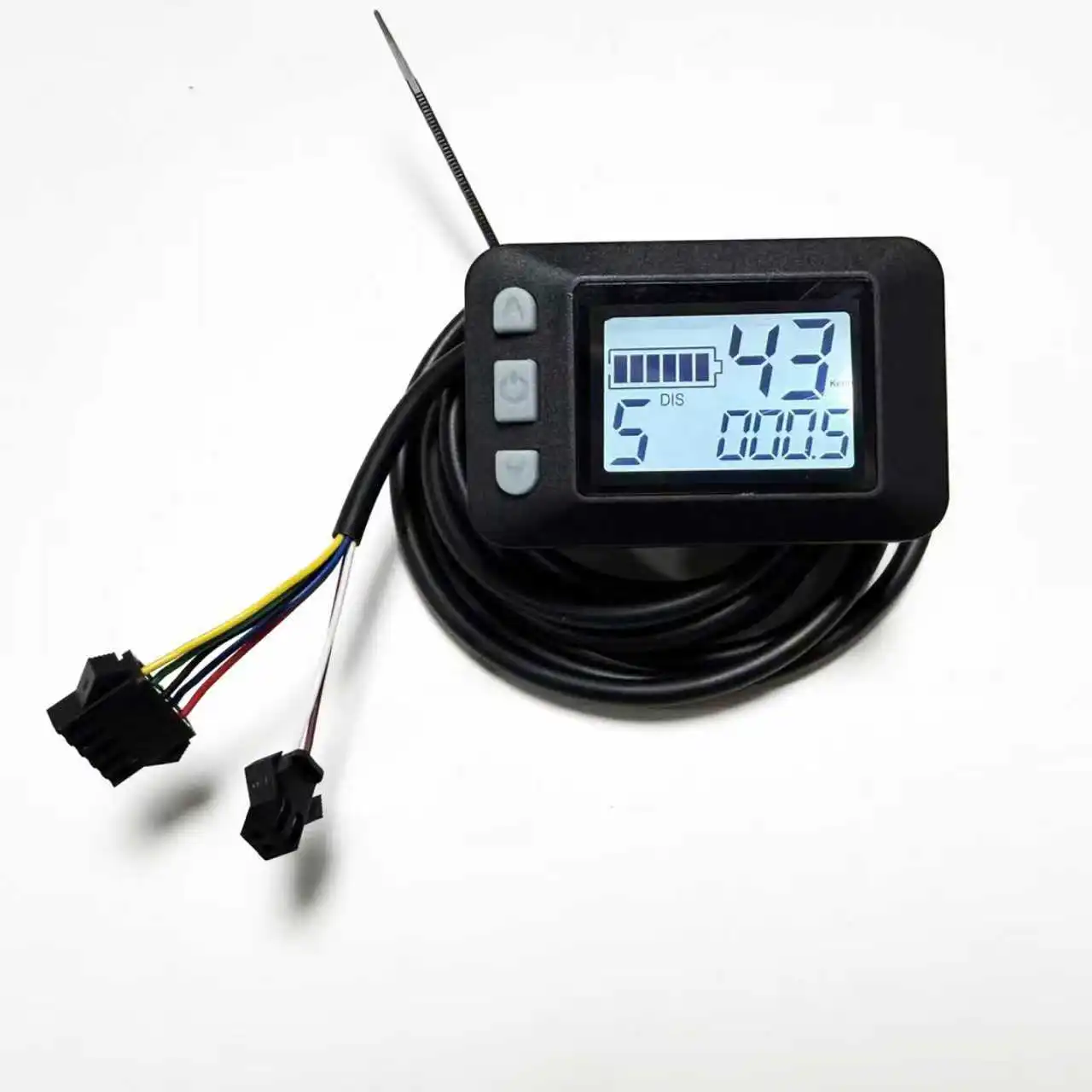
DC 24V 36V 48V 60V E-bike LCD Display Screen P3 LCD 0r HK811 Screen for UART NO.2 Serial Communication Protocol 22.2mm handlebar
DC 24V 36V 48V 60V E-bike LCD Display Screen P3 LCD 0r HK811 Screen for UART NO.2 Serial Communication Protocol 22.2mm handlebar
Couldn't load pickup availability
Note: This product is suitable for Protocol 2 controllers, 5+2 pin series. Only one meter is included; size is selectable.
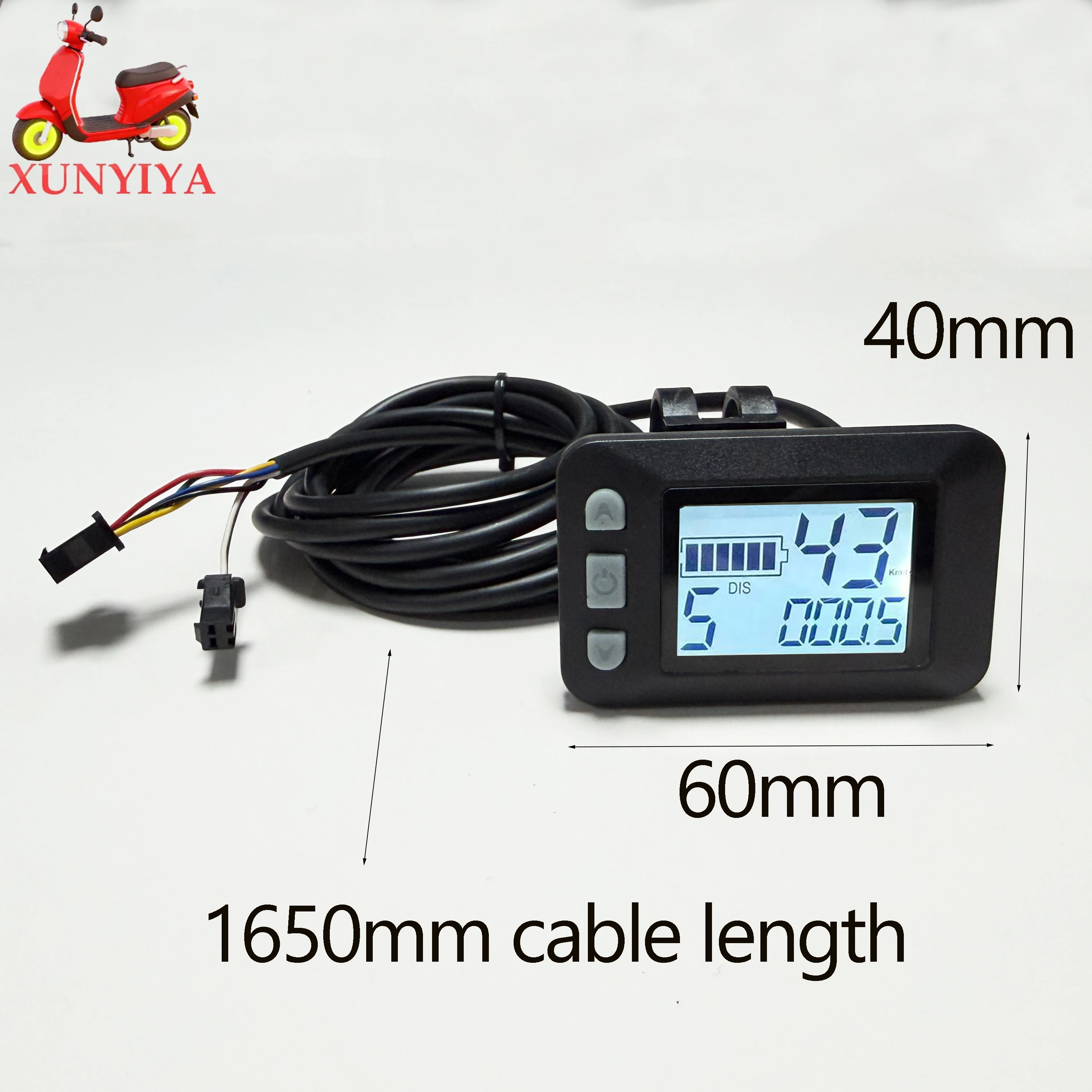
P3 60x40mm small lcd:
Size;60mmx40mm
 3. Communication Protocol: UART
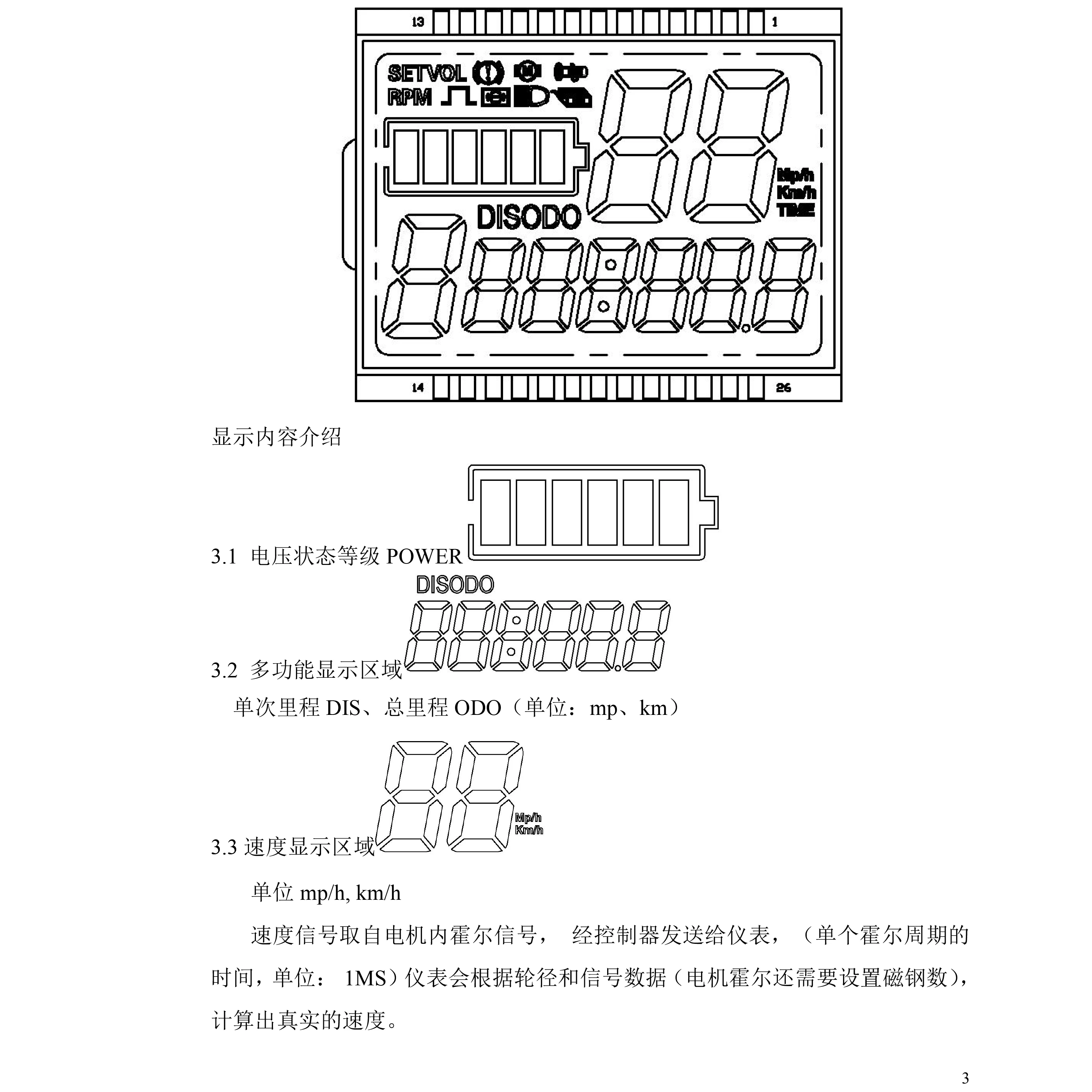
Full Display Content (Displays all content within 1 second of power-on)
Display Content Introduction
3.1 Voltage Status Level POWER
3.2 Multifunctional Display Area
Single Mileage DIS, Total Mileage ODO (Units: mp, km)
3.3 Speed Display Area
Units: mp/h, km/h
Speed signal is taken from the Hall effect signal inside the motor, sent to the instrument panel via the controller (time of a single Hall effect cycle, unit: 1ms). The instrument panel calculates the actual speed based on wheel diameter and signal data (motor Hall effect also requires setting the number of magnets).
3.4 Vehicle Main Gear Adjustment, adjustable from 0-3 and 0-5 gears;
3.5 Vehicle Status Display Area
Setting Mode
: Digital Voltage
: Brake Indication
: Motor Fault
: Throttle Fault
: Wheel Diameter
: Headlight
: Controller Fault
 4. Settings
P01: Backlight Brightness, Level 1 is dimmest, Level 3 is brightest;
P02: Speed Unit, 0: km/h; 1: mp/h;
P03: Voltage Level: 24V, 36V, 48V, default 36V;
P04: Sleep Time: 0, no sleep; other numbers are sleep time, range: 1-60; unit: minutes;
P05: Assist Levels: 0-3 mode, 0-5 mode;
P06: Wheel Diameter: unit: inch; precision: 0.1;
P07: Speed Measuring Magnet Count: Range: 1-255;
P08: Speed Limit: Range 0-100km/h, 100 indicates no speed limit;
1. Communication Status (Controller Control): Drive speed maintained at the set value,
Error: ±1km/h; (both power assist and throttle speed limit)
Note: The values here are based on kilometers. When the unit setting is changed from kilometers to miles, the speed value on the display interface will automatically convert to the correct miles value. However, the speed limit value set in this menu under the miles interface will not be converted and will be inconsistent with the actual displayed miles speed limit value;
P09: Zero Start/Non-Zero Start Setting, 0: Zero Start; 1: Non-Zero Start;
P10: Drive Mode Setting, 0: Power Assist Drive (the amount of power assistance is determined by the power assist gear; the throttle is ineffective in this mode).
1: Electric Drive (driven by the throttle; the power assist gear is ineffective in this mode).
2: Power Assist Drive and Electric Drive Coexist (electric drive is ineffective in zero start state).
P11: Assist Sensitivity Setting 1-24
P12: Assist Start Intensity Setting 0-5
P13: Assist Magnet Type Setting: 5, 8, or 12 magnets
P14: Controller Current Limit Setting: Default 12A, Range: 1-20A
P15: Controller Undervoltage Value
P16: Cruise Control Options: 0: Cruise Control Off, 1: Cruise Control On
P17: ODO Reset Setting: Press and hold the up button for 5 seconds to reset ODO.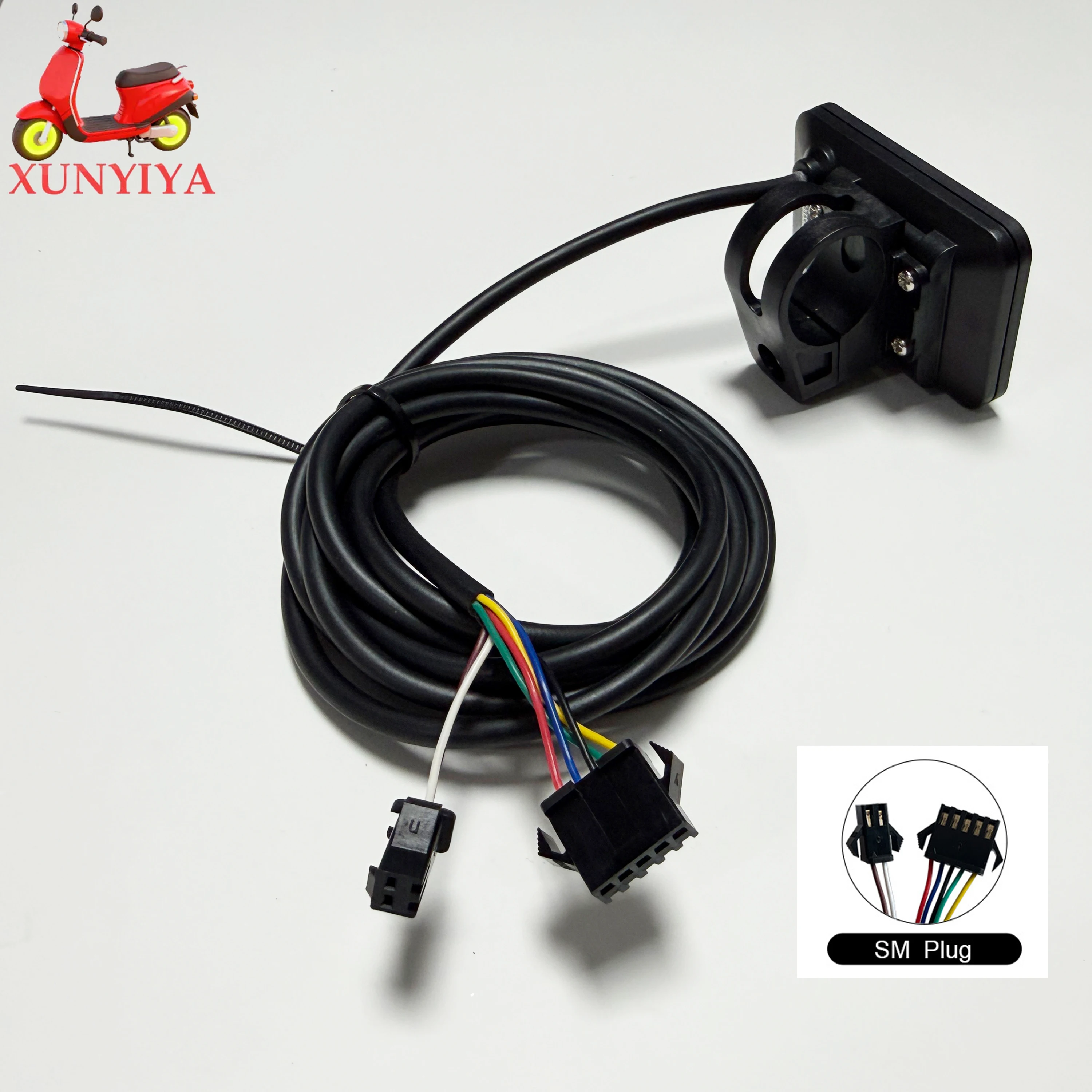 IV. Button Introduction
1. In the off state, press and hold the power button to turn on; after powering on, briefly press the power button to switch the interface between ODO, DIS, and VOL.
2. In the on state, press and hold the power button to turn off; press and hold the up button to turn on the headlights; press and hold the down button to enter 6KM cruise control; briefly press the up button to increase the power assist level by 1; briefly press the down button to decrease the power assist level by 1.
3. Press and hold the up button + down button to enter mode settings.
Parameter value modification: In a certain parameter state, briefly press the power button to switch parameters; briefly press the up button to increase the value; briefly press the down button to decrease the value. After modification, briefly press the power button to switch to the next parameter and save the previous parameter value; after parameter modification, press and hold the up button + down button again to exit the settings interface. If you do not press, wait 10 seconds for automatic exit and parameter saving.
Table: Standard Connector Wiring Sequence Table
Standard Wiring Sequence | Standard Wire Color | Function
1 Red (VCC) | Instrument power cable
2 Blue (DS) | Controller power control cable
3 Black (GND) | Instrument ground
4 Green (RX) | Instrument data receive cable
5 Yellow (TX) | Instrument data transmit cable
6 Brown (DD) | Instrument headlight cable
7 White (GND) | Headlight ground cable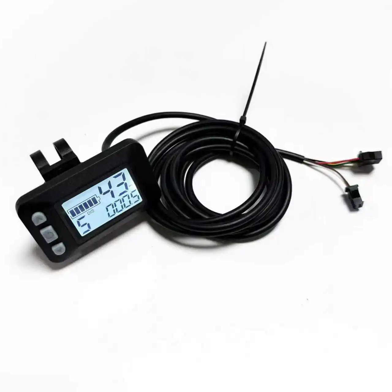
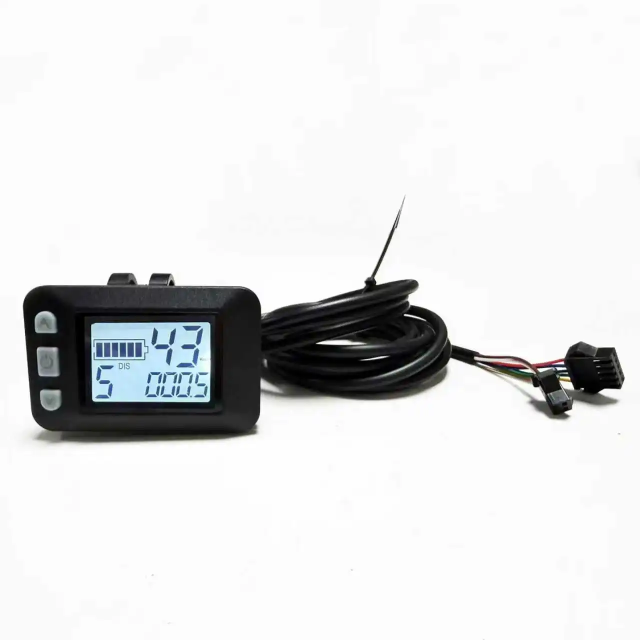
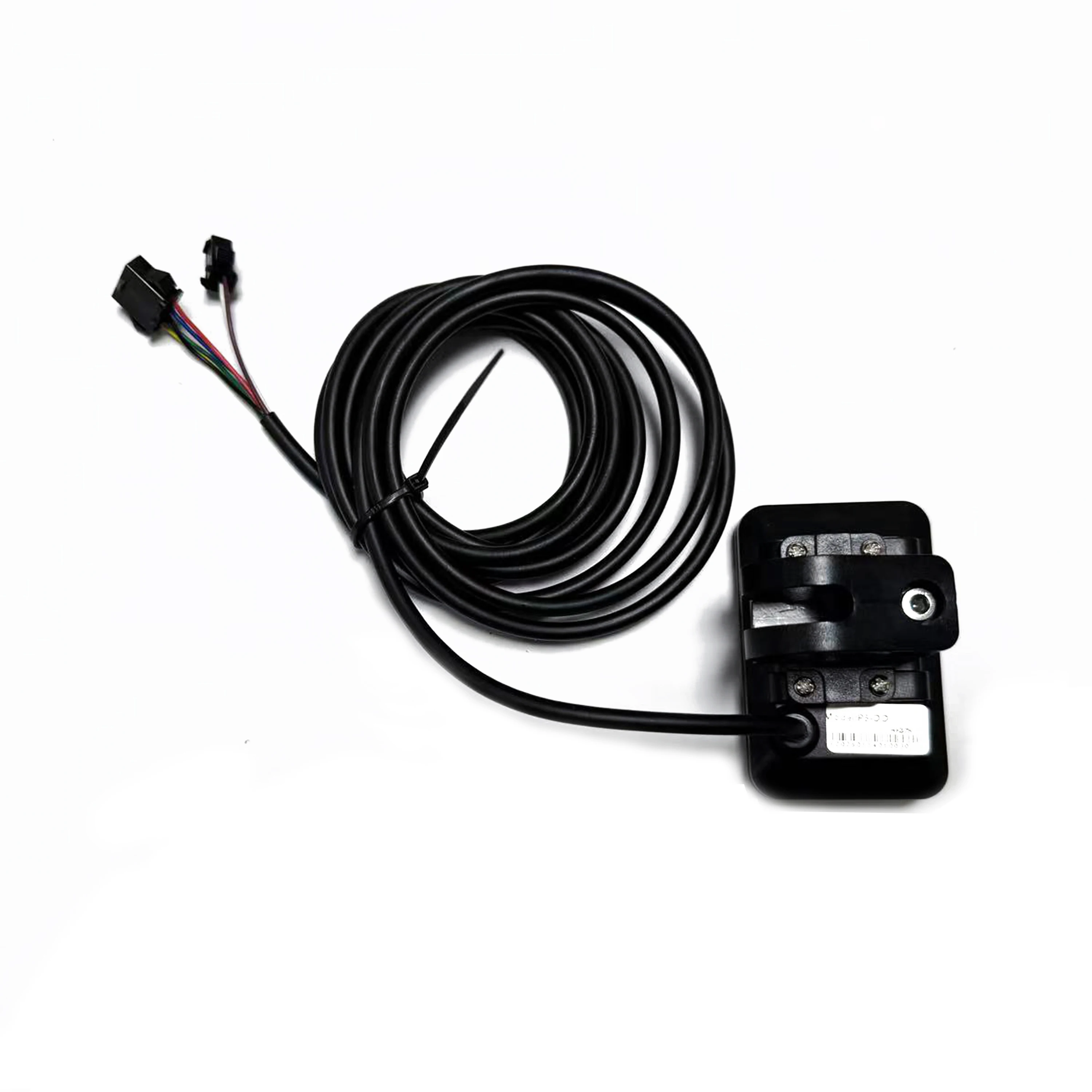
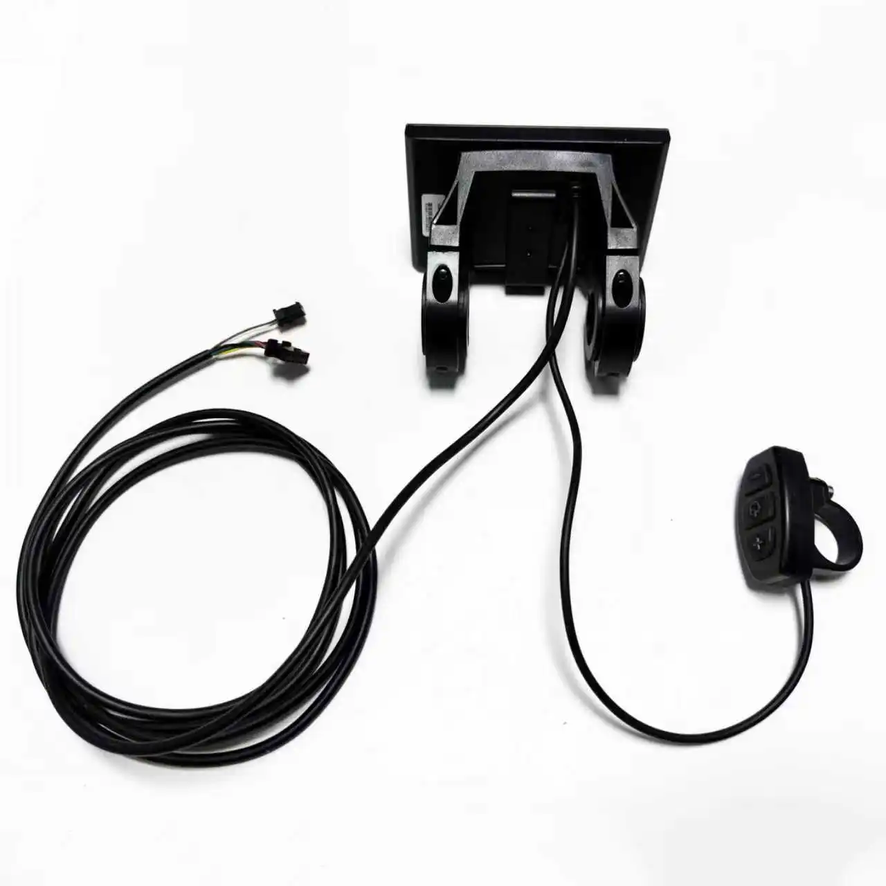
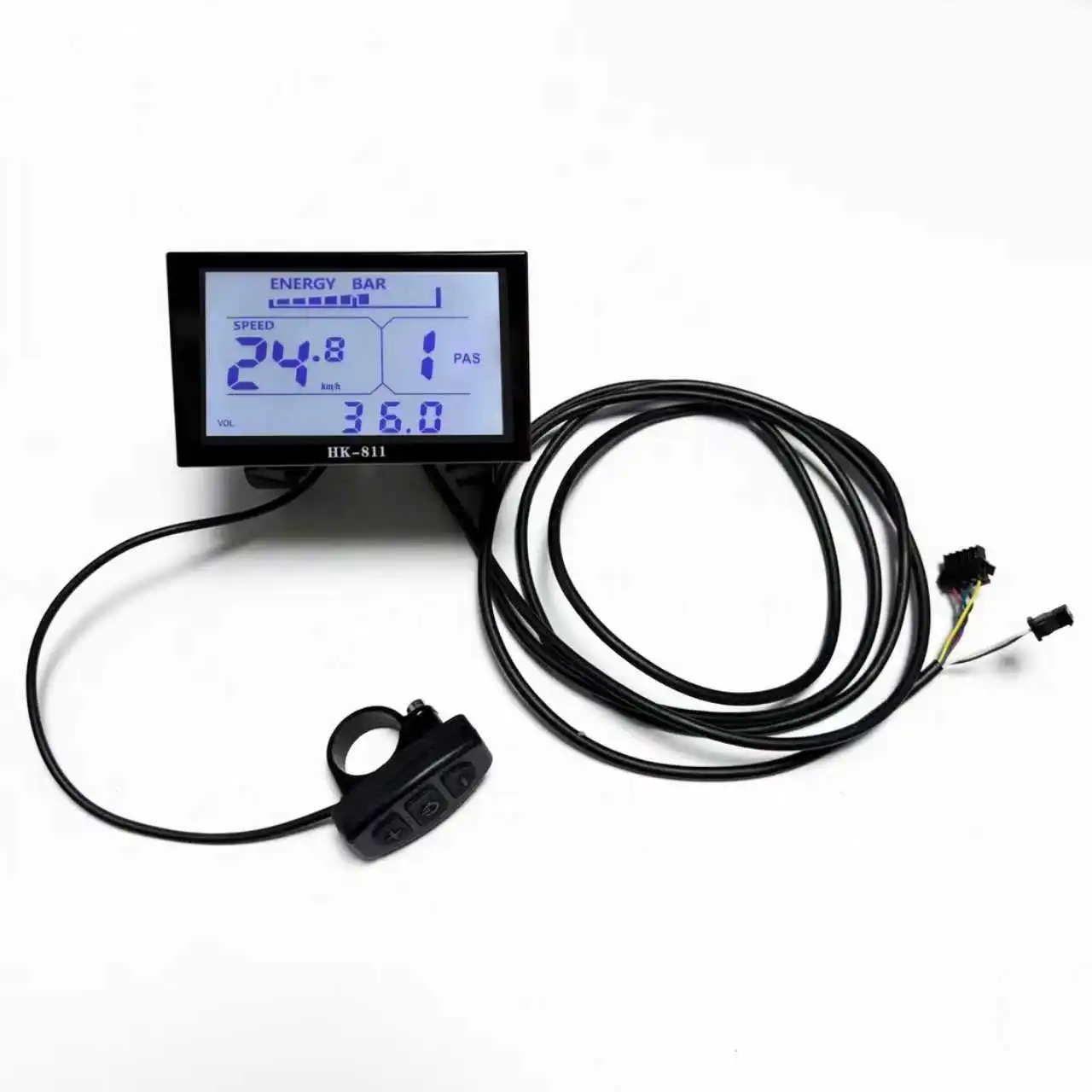
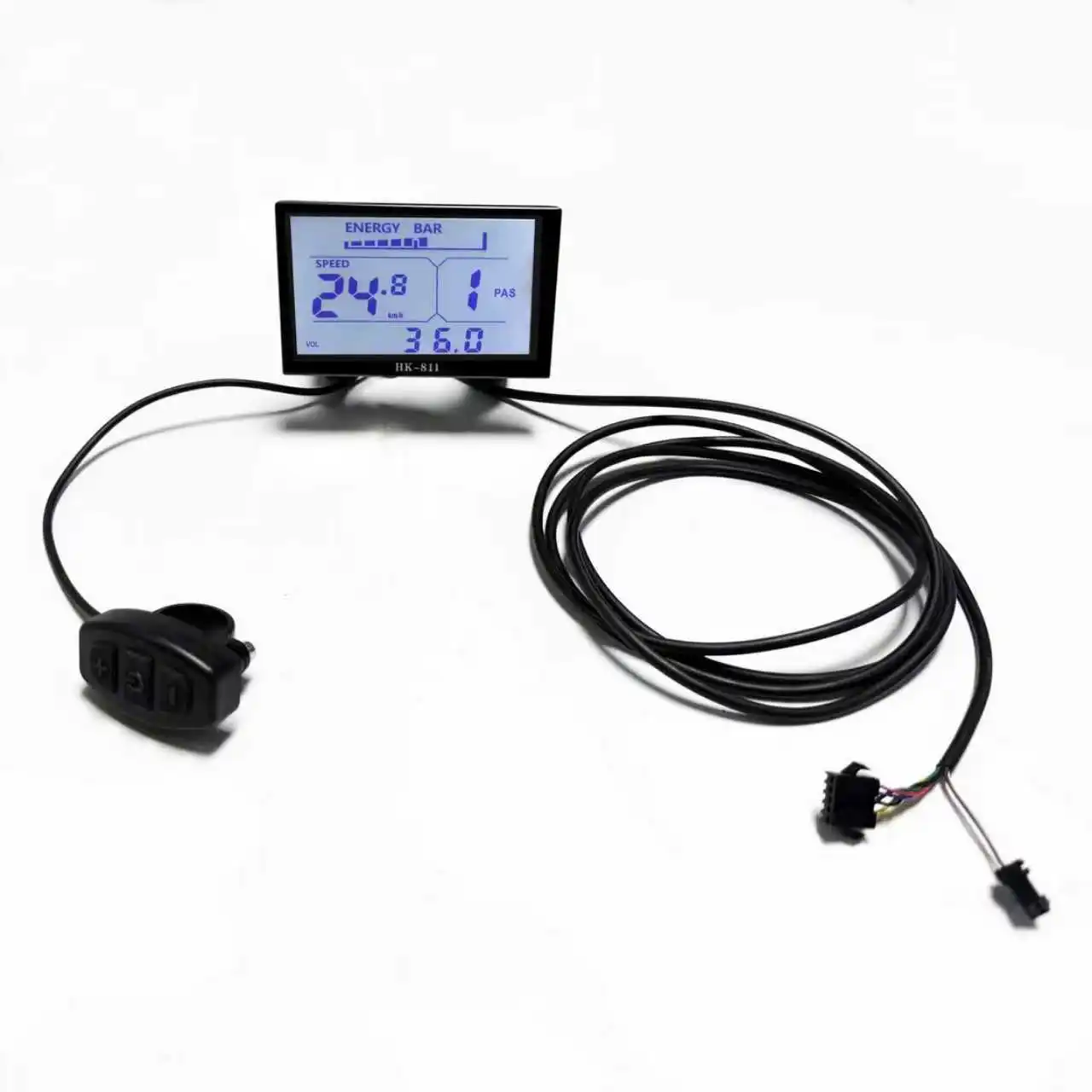
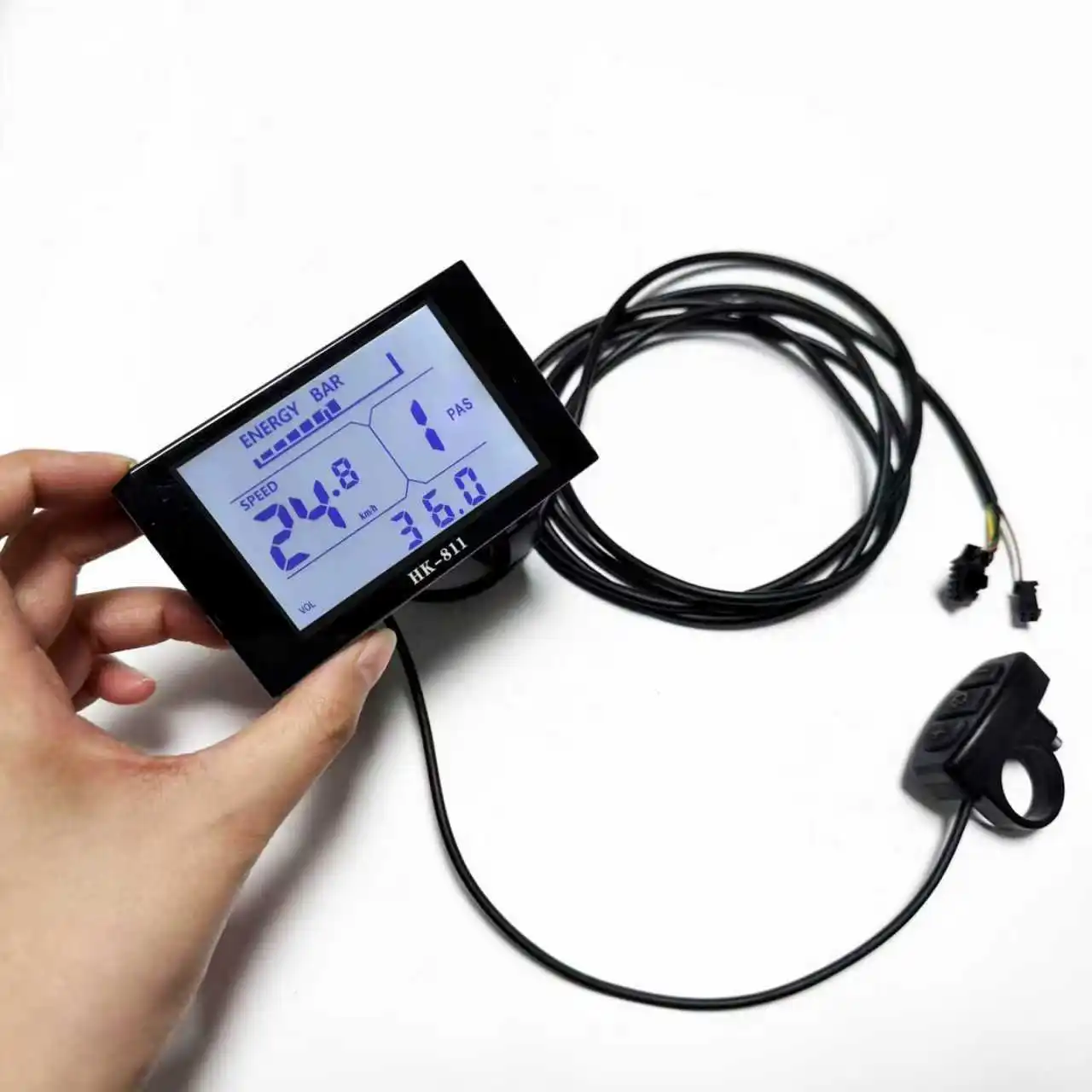
HK811 Horizontal Screen :HK811 monochrome LCD display
Size;95mmx55mm
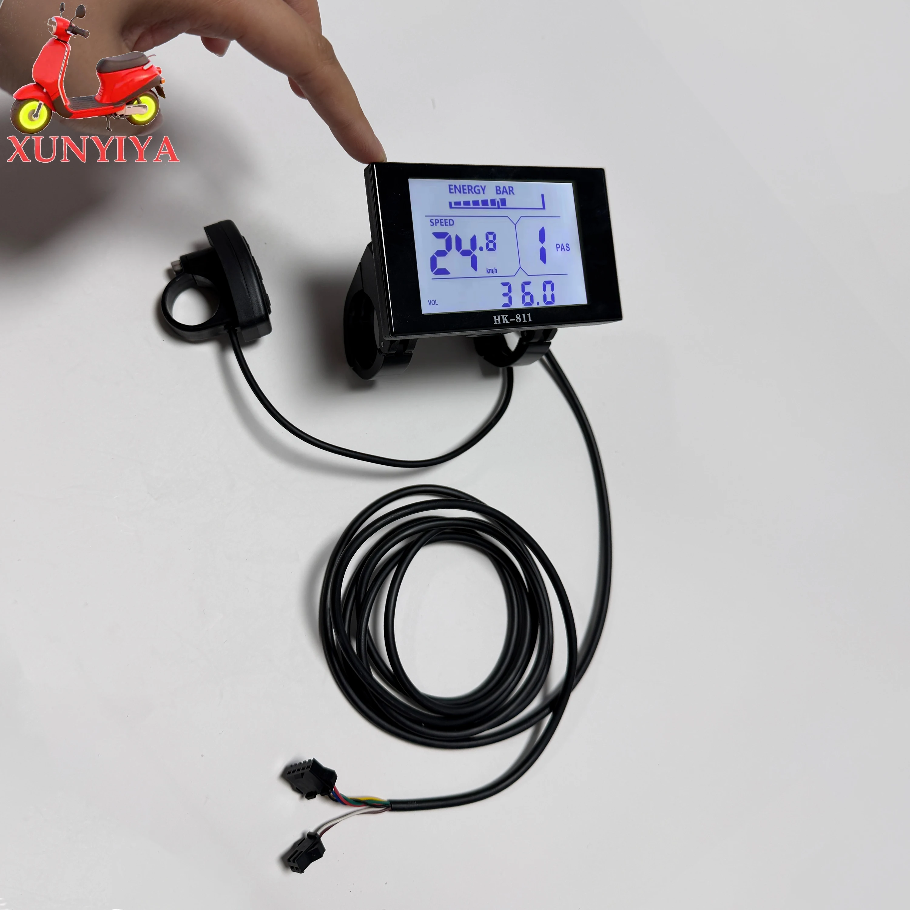 Settings
P01: Backlight brightness, level 1 is dimmest, level 3 is brightest, default is 2
P02: Mileage unit, 0: KM; 1: MILE
P03: Voltage level: 24V, 36V, 48V, default is 48V
P04: Sleep time: 0, no sleep; other numbers are sleep time, default is 10min, range: 1-60; unit is minutes
P05: Assist level: 3-level adjustable mode, 5-level adjustable mode
P06: Wheel diameter: unit, inch; accuracy: 0.1; adjustable range 5-50
P07: Speed Measuring Magnet Count: Range: 1-255
P08: Speed Limit: Range 0-100km/h, 100 indicates the maximum speed limit.
Communication Status (Controller Control): Drive speed maintained at the set value.
Error: ±1km/h; (both power assist and throttle speed limit)
Note: The values here are based on kilometers. When the unit setting is changed from kilometers to miles, the speed value on the display interface will automatically convert to the correct miles value. However, the speed limit value set in this menu under the miles interface will not be converted and will not match the actual displayed miles speed limit value.
P09: Zero Start/Non-Zero Start Setting, 0: Zero Start; 1: Non-Zero Start
P10: Drive Mode Setting, 0: Power Assist Drive (the amount of power assistance is determined by the power assist level; the throttle is ineffective in this mode)
1: Electric Drive (driven by the throttle; the power assist level is ineffective in this mode)
2: Power Assist Drive and Electric Drive Coexist (electric drive is ineffective in zero start state)
P11: Power Assist Sensitivity Setting, Range: 1-24
P12: Power Assist Start Intensity Setting Range: 0-5
P13: Assist Magnet Type Setting: 5, 8, or 12 magnets
P14: Controller Current Limit Setting: Default 12A, Range: 1-20A
P15: Controller Undervoltage Value
P16: Auto Cruise Setting: 0 - Auto cruise enabled, 1 - Auto cruise disabled; trigger time determined by the controller.
P17: ODO Reset Setting: Press and hold the up button for 5 seconds to reset ODO.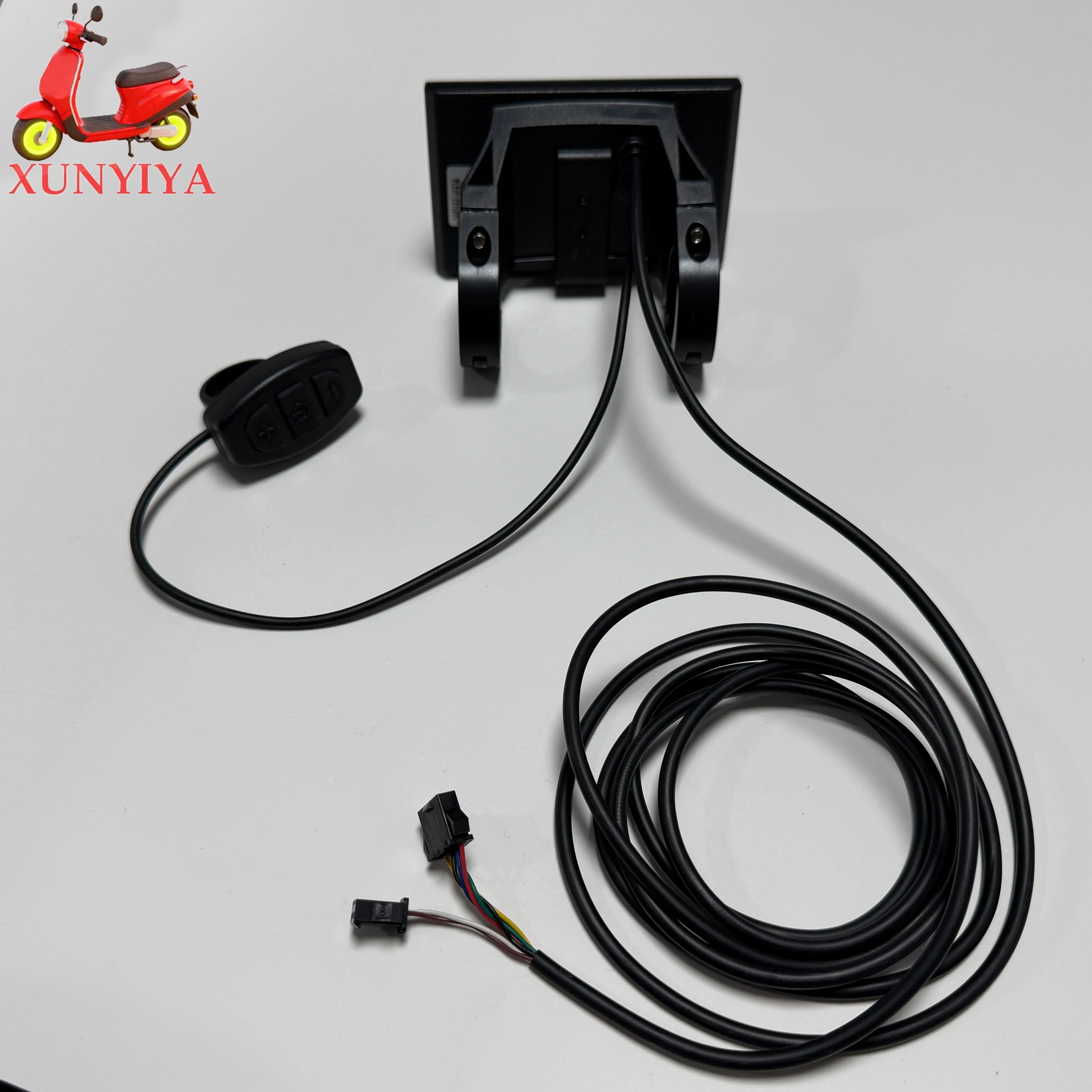
3.9 Vehicle Status Display Area
Status Code (Decimal) Status Meaning Remarks
0 Normal Status
1 Reserved
2 Brake Not displayed here
6 Low Battery Voltage
7 Motor Failure
8 Throttle Failure
9 Controller Failure
10 Communication Reception Failure
11 Communication Transmission Failure
12 BMS Communication Failure
1. Display Functions: Speed display, power steering indicator, battery level indicator, fault indication, total mileage, single trip mileage, single trip driving time display.
2. Control and Setting Functions: Power switch control, headlight switch control (output from controller), 6km/h inching control, wheel diameter setting, maximum speed setting, idle automatic sleep time setting, backlight brightness setting, voltage level setting.
3. Communication Protocol: UART. All display content (fully displayed within 1 second of power-on).
Table: Standard Connector Wiring Sequence Table
Standard Wiring Sequence | Standard Wire Color | Function
1 Red (VCC) | Instrument Power Supply Line
2 Blue (K) | Controller Power Control Line
3 Black (GND) | Instrument Ground Line
4 Green (RX) | Instrument Data Receive Line
5 Yellow (TX) | Instrument Data Transmit Line
I. Appearance and Materials
The product casing is made of ABS, and the LCD transparent window is made of tempered glass.
Size: 4.3-inch LCD screen
II. Operating Voltage and Wiring
1. Operating Voltage: DC 24V, 36V, 48V, 60V
isplay Content Description
3.1 Battery Level Display
3.2 Speed Display Area
Current Speed (SPEED), Maximum Speed (MAX), Average Speed (AVG), Vehicle Status Display Area (error)
Units: mp/h, km/h
The instrument panel calculates the actual speed based on wheel diameter and signal data.
3.3 Speeding
3.4 Vehicle Modes
Walk Cruise: Cruise Control Mode, Auto: Automatic Mode, Manual Mode (normally not displayed)
3.5 Assist Control Level Adjustment
Adjustable from 0-5 levels; typically 3 levels are available, with 5 levels selectable.
3.6 Headlights
3.7 Charging
3.8 Multi-function Display Area
Total Distance (ODO), Trip Distance, Current Voltage (VOL), Ride Time (TM)